PENTRU VERSIUNEA IN ROMANA APASA AICI
After the experiment on which I wrote here earlier, the one where I was able to watch and enjoy the duality of light as particle or wave, I tried to understand the way in which the diffraction pattern is influenced by the type of pinhole and it's creation.
I am convinced that everyone who practice pinhole photography has at least once had the curiosity to realize his own pinhole. So it has happened in my case. For some years I make my own pinholes.
The rule is simple: the hole follows the formula dc√ƒλ, the material should be as thin as technically possible and the hole circular and without burrs. Regarding the formula one does not have to be a mathematician to succeed: d is the pinhole diameter, c is a constant, ƒ is the focal length and λ is the wavelength of light for which the pinhole is calculated. For a simplified calculation anyone may turn to online computers or applications like those of Mr. Pinhole or Pinhole Designer.
Initially the process I used that was a difficult one, making multiple holes which I measured to determine which of my attempts have the accuracy needed to serve as "aperture."
In time I observed variations of the c constant at different photographers, starting with the amount determined by J. Petzval, reaching to 1.9 recommended by Lord Rayleigh till the one equal to 1.562 derived from this post. Since the value of the constant can wary, it's choosing can have significant impact on the pinhole diameter.
Let's take an example: for a 50 mm focal length we have:
332 µ for c = 2
315 µ for c = 1.9
259 µ for c = 1,562
166 µ for c = 1
This variation led me to look for dental instruments and extremely fine drills (multiple 50μ) for making the pinhole. In other words, if I encounter a situation where the camera I plan to build does not allow me to realize a predetermined focal length, I choose the closest value of the diameter based on the drills I have (ie. for both 259μ and 315μ I will choose to drill 300μ).
Below I review the impact had on the passage of light by the most common pinhole types:
POKED PINHOLE IN ALUMINUM FOIL
My first pinhole camera had a pinhole made in aluminum foil. Since one of the rules says that the pinhole material should be as thin as possible, and believing that I can punch a sufficiently "clean" hole, I chosen this material. Today I no longer use aluminium foil for the obvious reasons: it tears easily, it is unstable and may not be precisely drilled.
POKED PINHOLE IN AN ALUMINIUM SHEET, CAREFULLY
In my case the pinholes realized in aluminium sheet followed to those made in alu foil. I made them with a compass needle, with a soft support under the sheet. In this way I easily perforated sheet by consecutive rotations of the needle, and with a nail file I gently and evenly stroking the edge burr off.
Today still go back, when I am in a hurry, to good pinholes achieved in this way.
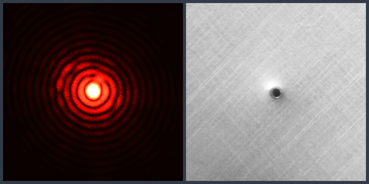
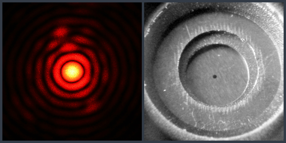
DRILLED PINHOLE IN ALUMINUM SHEET, WITH BEVELED EDGES.
This is how I realize pinholes now, for my use and for those who order pinholes. I use extremely fine drills and to avoid that the pinhole gets "cylindrical" or to have burrs on the perimeter, I use a spherical dental milling tool on both sides of the board, thereby obtaining a sharp pinhole edge.
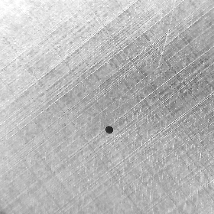
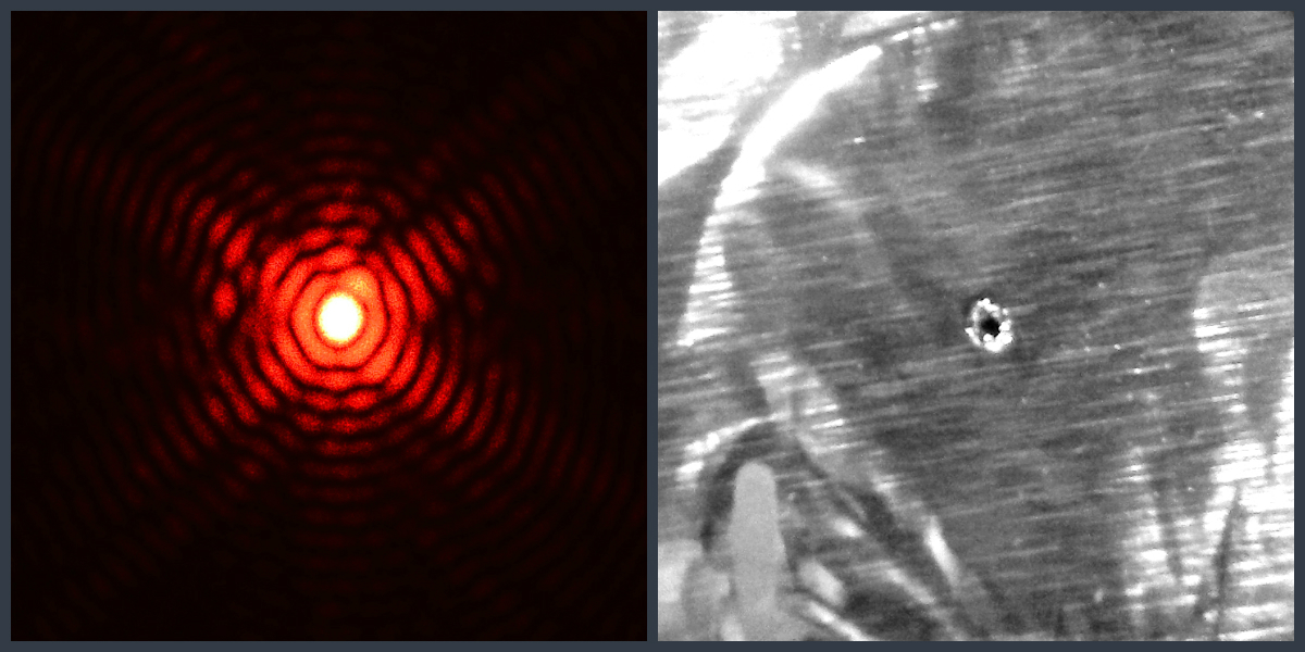
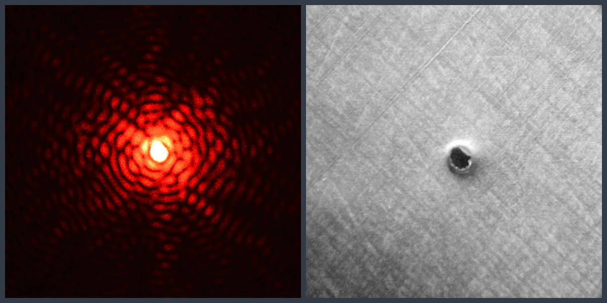
POKED PINHOLE IN ALUMINUM SHEET, CARELESSLY
Out of curiosity I wanted to see what happens with the diffraction pattern in relation to beer cans, so common used in solargraphy, namely a hole practiced sloppy with a sewing needle. The pattern speaks for itself.
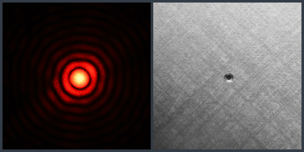
BOUGHT PINHOLE – HOLGA 120WPC
To have a benchmark in terms of the pinholes from above I checked the diffraction pattern from my Holga camera 120WPC. It's pinhole is made with precision devices. I was glad to see that my hand made approach is superior to the industrial one.
Here you can find out how I did we get to experiment with laser. My following post will show what happens when you expose photographic paper to a a 5000mw green laser, how a single or double slit diffraction pattern looks like and what 2 adjacent pinhole diffraction pattern look like.


